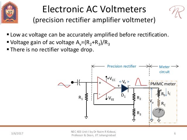
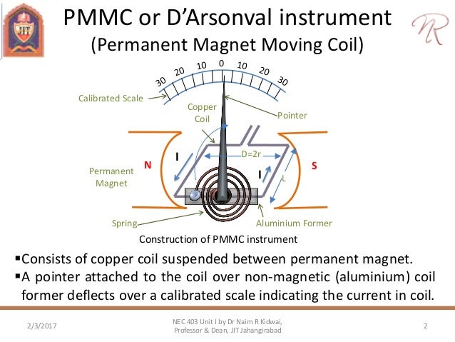
Two types of PMMC meter used in AC measurement: 1. Half wave rectification 2. Full wave rectification. 10 DArsonval meter movement used with half wave rectification To convert alternating current (AC) to unidirectional current flow, which produces positive deflection when passed through a PMMC, the diode rectifier is used. The permanent magnet moving coil (PMMC) instrument is an electromechanical meter that can be connected with additional components to function as an ammeter, a voltmeter, or an ohmmeter. Figure 1 shows the basic construction of a PMMC instrument. Permanent Magnet Moving Coil Mechanism (PMMC) In PMMC meter or (D’Arsonval) meter or galvanometer all are the same instrument, a coil of fine wire is suspended in a magnetic field produced by permanent magnet. According to the fundamental law of electromagnetic force, the coil will rotate in the magnetic field when it. PMMC ammeter have uniform scale because of eddy current damping they are spring controlled their deflecting torque varies directly as current both spring controlled and having deflecting torque varies directly as current 2. PMMC meter is fitted in Ammeter Voltmeter Multimeter Wattmeter 3. In a PMMC instrument, the damping provided is Air damping Fluid. The PMMC meter is connected between the source terminals of the FETs, representing two opposite corners of the bridge. In the absence of input signal, the gate terminals of the FETs are at ground potential and the transistors operate under identical quiescent conditions.
- Electronic Measuring Instruments
- Useful Resources

- Selected Reading
DC voltmeter is a measuring instrument, which is used to measure the DC voltage across any two points of electric circuit. If we place a resistor in series with the Permanent Magnet Moving Coil (PMMC) galvanometer, then the entire combination together acts as DC voltmeter.
The series resistance, which is used in DC voltmeter is also called series multiplier resistance or simply, multiplier. It basically limits the amount of current that flows through galvanometer in order to prevent the meter current from exceeding the full scale deflection value. The circuit diagram of DC voltmeter is shown in below figure.

We have to place this DC voltmeter across the two points of an electric circuit, where the DC voltage is to be measured.
Apply KVL around the loop of above circuit.
$V-I_{m}R_{se}-I_{m}R_{m}=0$ (Equation 1)
$$Rightarrow V-I_{m}R_{m}=I_{m}R_{se}$$
$$Rightarrow R_{se}=frac{V-I_{m}R_{m}}{I_{m}}$$
$Rightarrow R_{se}=frac{V}{I_{m}}-R_{m}$ (Equation 2)
Where,
$R_{se}$ is the series multiplier resistance
$V$ is the full range DC voltage that is to be measured
$I_{m}$ is the full scale deflection current
$R_{m}$ is the internal resistance of galvanometer
The ratio of full range DC voltage that is to be measured, $V$ and the DC voltage drop across the galvanometer, $V_{m}$ is known as multiplying factor, m. Mathematically, it can be represented as
$m=frac{V}{V_{m}}$ (Equation 3)
From Equation 1, we will get the following equation for full range DC voltage that is to be measured, $V$.
$V=I_{m}R_{se}+I_{m}R_{m}$ (Equation 4)
The DC voltage drop across the galvanometer, $V_{m}$ is the product of full scale deflection current, $I_{m}$ and internal resistance of galvanometer, $R_{m}$. Mathematically, it can be written as
$V_{m}=I_{m}R_{m}$ (Equation 5)
Substitute, Equation 4 and Equation 5 in Equation 3.
$$m=frac{I_{m}R_{se}+I_{m}R_{m}}{I_{m}R_{m}}$$
$Rightarrow m=frac{R_{se}}{R_{m}}+1$
$Rightarrow m-1=frac{R_{se}}{R_{m}}$
$R_{se}=R_{m}left (m-1 right )$(Equation 6)
We can find the value of series multiplier resistance by using either Equation 2 or Equation 6 based on the available data.
Multi Range DC Voltmeter
In previous section, we had discussed DC voltmeter, which is obtained by placing a multiplier resistor in series with the PMMC galvanometer. This DC voltmeter can be used to measure a particular range of DC voltages.
If we want to use the DC voltmeter for measuring the DC voltages of multiple ranges, then we have to use multiple parallel multiplier resistors instead of single multiplier resistor and this entire combination of resistors is in series with the PMMC galvanometer. The circuit diagram of multi range DC voltmeter is shown in below figure.
We have to place this multi range DC voltmeter across the two points of an electric circuit, where the DC voltage of required range is to be measured. We can choose the desired range of voltages by connecting the switch s to the respective multiplier resistor.
Let, $m_{1},m_{2}, m_{2} $ and $m_{4}$ are the multiplying factors of DC voltmeter when we consider the full range DC voltages to be measured as, $V_{1} , V_{2}, V_{3}$ and $V_{4}$ respectively. Following are the formulae corresponding to each multiplying factor.
$$m_{1}=frac{V_{1}}{V_{m}}$$
$$m_{2}=frac{V_{2}}{V_{m}}$$
$$m_{3}=frac{V_{3}}{V_{m}}$$
$$m_{4}=frac{V_{4}}{V_{m}}$$
In above circuit, there are four series multiplier resistors, $R_{se1}, R_{se2}, R_{se3}$ and $R_{se4}$. Following are the formulae corresponding to these four resistors.
$$R_{se1}=R_{m}left (m_{1}-1 right )$$
$$R_{se2}=R_{m}left (m_{2}-1 right )$$
$$R_{se3}=R_{m}left (m_{3}-1 right )$$
$$R_{se4}=R_{m}left (m_{4}-1 right )$$
So, we can find the resistance values of each series multiplier resistor by using above formulae.
Definition: The instruments which use the permanent magnet for creating the stationary magnetic field between which the coilmoves is known as the permanent magnet moving coil or PMMC instrument. It operates on the principle that the torque is exerted on the moving coil placed in the field of the permanent magnet. The PMMC instrument gives the accurate result for DC measurement.
Construction of PMMC Instrument
The moving coil and permanent magnet are the main part of the PMMC instrument. The parts of the PMMC instruments are explained below in details.
Pmmc Meter
Moving Coil – The coil is the current carrying part of the instruments which is freely moved between the stationary field of the permanent magnet. The current passes through the coil deflects it due to which the magnitude of the current or voltage is determined. The coil is mounted on the rectangular former which is made up of aluminium. The former increases the radial and uniform magnetic field between the air gap of the poles. The coil is wound with the silk cover copper wire between the poles of a magnet.
The coil is mounted on the rectangular former which is made up of aluminium. The former increases the radial and uniform magnetic field between the air gap of the poles. The coil is wound with the silk cover copper wire between the poles of a magnet.
Magnet System – The PMMC instrument using the permanent magnet for creating the stationary magnets. The Alcomax and Alnico material are used for creating the permanent magnet because this magnet has the high coercive force (The coercive force changes the magnetisation property of the magnet). Also, the magnet has high field intensities.
Pmc Meter Stand
Control – In PMMC instrument the controlling torque is because of the springs. The springs are made up of phosphorous bronze and placed between the two jewel bearings. The spring also provides the path to the lead current to flow in and out of the moving coil. The controlling torque is mainly because of the suspension of the ribbon.
Damping – The damping torque is used for keeping the movement of the coil in rest. This damping torque is induced because of the movement of the aluminium core which is moving between the poles of the permanent magnet.
Pointer & Scale – The pointer is linked with the moving coil. The pointer notices the deflection of the coil, and the magnitude of their deviation is shown on the scale. The pointer is made of the lightweight material, and hence it is easily deflected with the movement of the coil. Sometimes the parallax error occurs in the instrument which is easily reduced by correctly aligning the blade of the pointer.
Torque Equation for PMMC Instrument
The deflecting torque induces because of the movement of the coil. The deflecting torque is expressed by the equation shown below.
Where, N – Number of turns of coil
B – flux density in the air gap
L, d – the vertical and horizontal length of the side.
I – current through the coil.
The spring provides the restoring torque to the moving coil which is expressed as

Where K = Spring constant.
For final deflection, By substituting the value of equation (1) and (3) we get,
The above equation shows that the deflection torque is directly proportional to the current passing through the coil.
Error in PMMC Instruments
In PMMC instruments the error occurs because of the ageing and the temperature effects of the instruments. The magnet, spring and the moving coil are the main parts of the instruments which cause the error. The different types of errors of the instrument are explained below in details.
1. Magnet – The heat and vibration reduce the lifespan of the permanent magnet. This treatment also reduced the magnetism of the magnet. The magnetism is the property of the attraction or repulsion of the magnet. The weakness of the magnet decreases the deflection of the coil.
2. Springs – The weakness of the spring increases the deflection of moving coil between the permanent magnet. So, even for the small value of current, the coil show large deflection. The spring gets weakened because of the effect of the temperature. One degree rise in temperature reduces the 0.004 percent life of the spring.
3. Moving Coil – The error exists in the coil when their range is extended from the given limit by the use of the shunt. The error occurs because of the change of the coil resistance on the shunt resistance. This happens because the coil is made up of copper wire which has high shunt resistance and the shunt wire made up of Magnin has low resistance.
To overcome from this error, the swamping resistance is placed in series with the moving coil. The resistor which has low-temperature coefficient is known as the swamping resistance. The swamping resistance reduces the effect of temperature on the moving coil.
Advantages of PMMC Instruments
The following are the advantages of the PMMC Instruments.
- The scale of the PMMC instruments is correctly divided.
- The power consumption of the devices is very less.
- The PMMC instruments have high accuracy because of the high torque weight ratio.
- The single device measures the different range of voltage and current. This can be done by the use of multipliers and shunts.
- The PMMC instruments use shelf shielding magnet which is useful for the aerospace applications.
Disadvantages of PMMC Instruments
The following are the disadvantages of the PMMC instruments.
- The PMMC instruments are only used for the direct current. The alternating current varies with the time. The rapid variation of the current varies the torque of the coil. But the pointer can not follow the fast reversal and the deflection of the torque. Thus, it cannot use for AC.
- The cost of the PPMC instruments is much higher as compared to the moving coil instruments.
The moving coil itself provides the electromagnetic damping. The electromagnetic damping opposes the motion of the coil which is because of the reaction of the eddy current and the magnetic field.
Related terms:
